Stress Analysis Crane Project
Project Description
The objective of this project is to design and build a mechanism that is powered by a standard servomotor, which will lift a cylindrical weight. Our mechanism is to be clamped in a given position while the other end lifts a weight that slides along a vertical post. Between the clamping area for the base of our design and the post holding the weight sits an obstacle. The mechanism may not touch the obstacle or any other surface besides the base and the sliding weight.
The design was limited to a maximum of 20 oz. and there were two catagories to compete in. One was to lift the weight the highest distance. The other was to have the lightest design that satisfied the requirements.
Teammates
The Design Process
 Going into the first design review, we assumed that the arm itself was massless.
This is neither practical nor possible, but we chose to runw ith it because the
center of mass of the arm was so close to the axis of rotation-- thus the moment
caused by the arm itself was negligible compared to the torque of the servo, the
weight of the counterweight, and the force due to the weight.
Going into the first design review, we assumed that the arm itself was massless.
This is neither practical nor possible, but we chose to runw ith it because the
center of mass of the arm was so close to the axis of rotation-- thus the moment
caused by the arm itself was negligible compared to the torque of the servo, the
weight of the counterweight, and the force due to the weight.
Additionally, we assumed that the arm would lift a max of 60 degrees. Although the servo was capable of rotating further, as the arm increased in angle, the change in x position due to trigonometric properties would cause the arm to no longer be ablle to lift the weight. As a result, a 60% lift angle would be a safe bet for the actual max lift angle. Lastly, we assumed that the max torque by the servo was 57 oz-in. After some prototyping, we discovered that we weren't getting anywhere near that torque despite that was what the manufacturer rated the servo for.
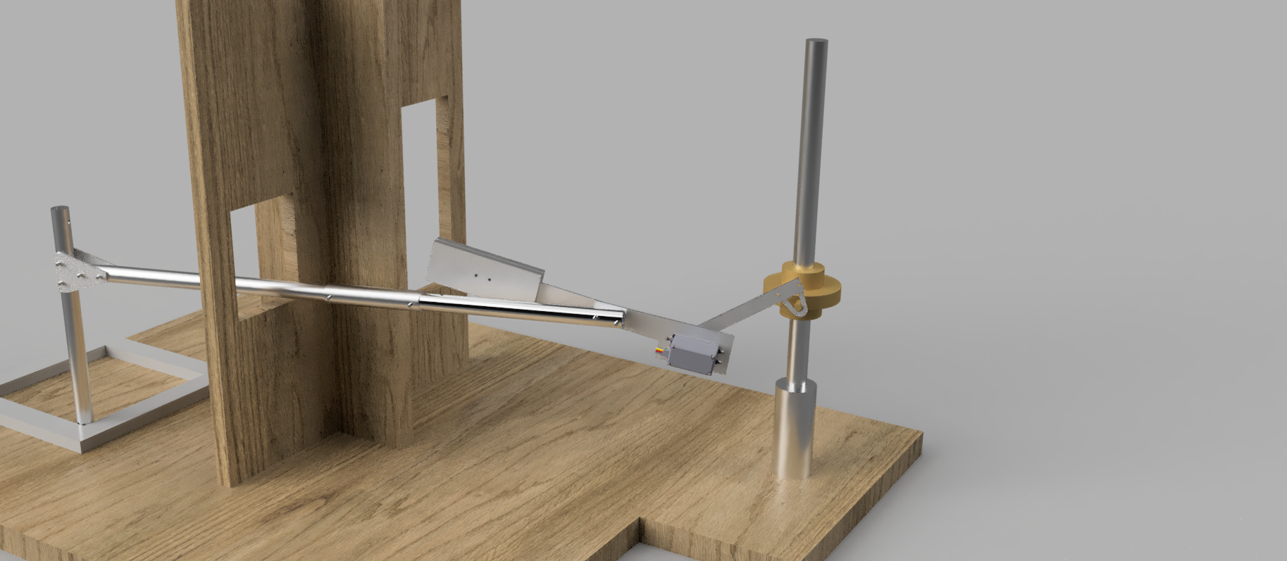
Once we were happy with our conceptual design, we used Solidworks to model the crane in an assembly. This allowed us to perform some basic simulations to determine the deflection at the end of the crane as well as its structural validity. These calculations helped determine what the inner and outer diameter of our structural members needed to be.
Manufacturing
After coming up with our design and running our digital simulations, we took our materials into the shop and began working. One of the constraints of the project was that we could only purchace solid aluminum stock. So, in order to manufacture a cylindrical based design that would be good at resisting bending, torsion, and buckling, we would need to manufacture hollow tubes ourselves.
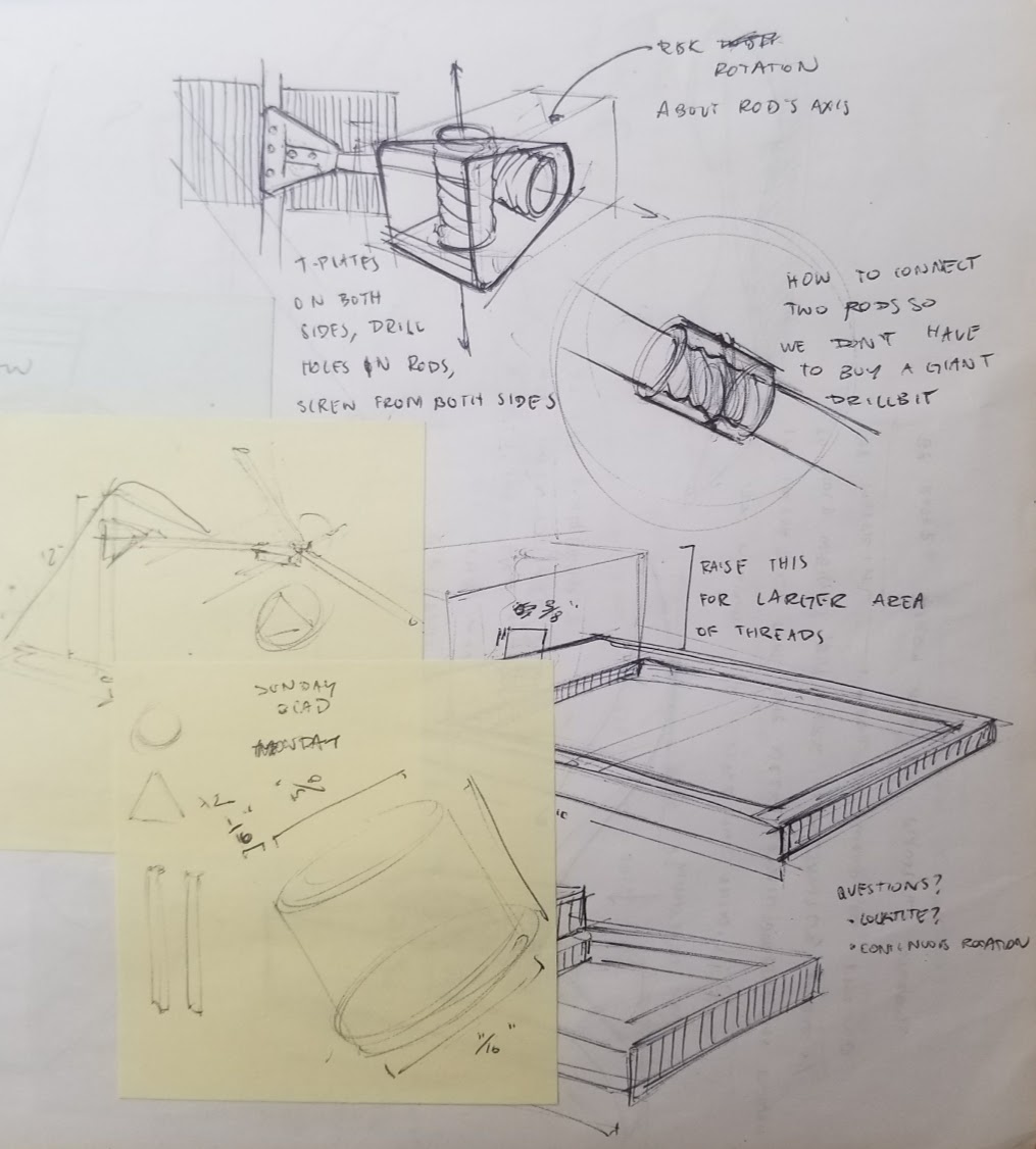
We then also manufactured a custom T-plates that allowed us to mount the tubes at right angles. We also had to make a custom bracket on the mill to allow for the servo to interface with the rest of the crane.
Design Review I
We were getting essentially 2 inches of height up until the night before the first design review. The main source of error that we encountered was the fact that the servo we were using was not consistent. Not only did we see different capabilities between different controllers, but also when we began the design review, we realized that the servo was performing at a reduced level compared to the night before. Our suspicions were confirmed when we switched servos and our crane performed better.
The actual output of our crane was much worse than the calculations that we did to find our theoretical servo torque as well as our theoretical lift height. Initially we calculated that using a counterweight that had its center of mass six inches from the axis of rotation would provide plenty of torque to allow for the servo to easily lift the weight. Unfortunately, when we placed our design on the field, we quickly found that the arm could barely lift the weight and that the crane was nowhere near the 2 inches that we needed to achieve.
Final Design
Coming out of the first review, we added a 45 degree bend in the lever arm and improved our counterweight so it would no longer hit our crane arm. Additionally, we milled a smaller base that allowed for more adjustability when it came to iterating for our final version.
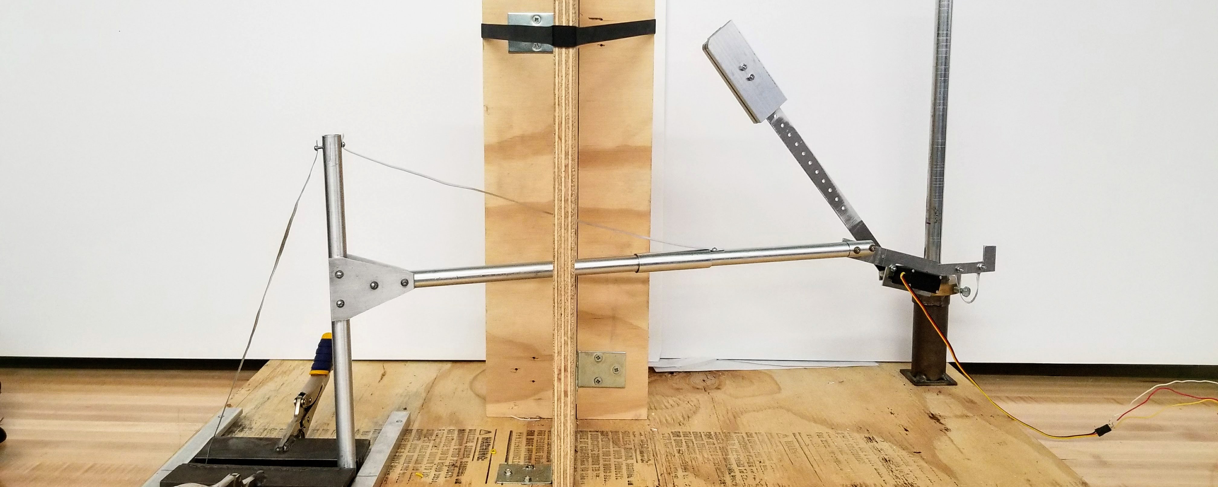
Our final crane was extremely adjustable in terms of rotation as well as adjusting our servo mount to get the arm to interact with the weight at the correct angle. Hollowed rods allowed for us to minimize weight without sacrificing structural integrity, especially in respect to bending.The tension strips that were instrumental in preventing further bending as it prevented bending for the first 60% of the crane arm length. The angled arm allowed for the weight to be lifted at a larger distance from the servo while still allowing the servo to cotrol the arm at the beginning.
As a group we were able to design and manufacture a crane that lifted the weight 4.875 inches which was second in the class.